Valve Adjustment (VTX 1800)
Posted by Bare | Last Updated August 17, 2013This is a walk-through for adjusting the valves on the VTX 1800. This is a tedious procedure which may not be for everyone, so if you don’t like to turn wrenches, get easily frustrated to the point of throwing tools, or you have very little mechanical skill then this job may be best left for the pros. If you’re unsure about undertaking this procedure then my advice would be to read this walk-through multiple times, watch the video (at the bottom), and see how comfortable you feel with the steps before actually getting into the job. My intent here isn’t to scare anyone off, but this is probably the most tedious job an average wrench/rider could undertake without professional help.
Standard disclaimer: As always, you undertake this project at your own risk!
The time involved in this project should be anywhere from 2-4 hours depending on your skill level with a wrench. If this is your first time adjusting valves and you’re uncertain about the procedure then I’d consider setting aside a Saturday or Sunday afternoon in case an unexpected snag causes delays.
If you haven’t already, I can’t stress how much easier it will make this job to do the desmog. The smog system consists of hoses, wires and a lot of other junk that gets in the way while you’re trying to work and makes you say things you shouldn’t say in front of your kids… In fact, this entire write-up is detailed as if you have already desmogged the bike, which is even more reason why I HIGHLY recommend doing the desmog during the tear-down of the bike before you begin the valve adjustment process.
This is how much junk the desmog will get out of your way:

|

|

Why do we have to adjust the valves on the VTX?
I know what you’re thinking – “I don’t have to adjust the valves on my car, so why didn’t Honda use the same technology on my bike?” It is true that almost all vehicles and a lot of motorcycles made today do have auto-adjusting valve lifters or auto-slack adjusters in the valve train – so why? One word – POWER. It takes energy from the engine to do this auto-adjusting, so if you put 2 identical engines side by side with auto-adjusting valves in one and manually adjusted valves in the other, the engine with manually adjusted valves will make more power than the other. How much power are we talking about? When Honda changed to manually adjusted valves on the Valkyrie in the 90’s it gained 10HP.
Other factors I’m sure Honda considered when designing the VTX engine was the overall height of the engine. If you use auto-adjusting lifters in an engine then the rocker boxes need to be taller to accommodate the lifters in the valve train. This means the frame’s backbone would have to be taller and this is not what you want when you’re trying to build a low slung cruiser.
Not to get too technical, but it also takes a lot more oil pressure than the VTX’s 7 PSI (at idle) to keep hydraulic lifters pumped up – you would need 6 lifters if you were going to have auto-adjusting valves on the VTX. To those that might recommend changing the rocker arm ratio for improved engine performance, the VTX engine has one end of the rocker sitting directly on the camshaft lobe and the other end of the rocker sitting on top of the valve stem so there is no way to change the rocker arm’s lift ratio.
What all of this means is that Honda made a trade-off… We want to have a VTX (1800) which makes 85-100 HP depending on bolt on parts (pipes, intake, fuel manager) and without these manually adjustable valves we just couldn’t have that.
Required tools/Materials
- Tools to remove seat
- Tools to remove gas tank
- 8mm wrench (5/16″ will work also), an 8mm 1/4″ drive socket/ratchet comes in handy but is not required
- Socket wrench & extension
- 10mm, 17mm & spark plug sockets
- 5 & 6mm allen
- 10mm offset wrench (see details below under “Tools“)
- 4mm tappet wrench (see details below under “Tools“)
- .004″, .005″, .006″, .012″, .013″, & .014″ feeler gauges (see details below under “Tools“)
- Torque wrench capable of 13-16 ft/lbs
- A few feet of string
- Silicone grease or a few drops of clean engine oil
- Dielectric grease
- Anti-sieze
- Flashlight
- (Optional) motorcycle lift – it just makes the job a little easier
If you still have the stock airbox you’ll need:
- A good #2 philips screwdriver, possibly an impact driver (for removing stock airbox)
Tools
The list above gives a fairly detailed and accurate description of what tools you’ll need to complete this job, but let’s break down the specific tools you’ll use to inspect and adjust the valves in a little more detail so you can have your tools ready before you open up the bike.
I’m not trying to push Craftsman tools, I reference them only because they are easily
available to pretty much everyone at Sears or through the Sears website.
Here are the tools we need for adjusting the valves:

- 10mm offset wrench – this is pretty straight-forward. We need an offset 10mm to get to the valve locknuts as they set down in the inspection area below the opening in the head. Even if you use a 10mm socket to break the locknut loose you still use the 10mm offset to hold the locknut in place as you adjust with the 4mm wrench.
- 4mm tappet wrench – if you adjust a lot of valves you may find it worthwhile to buy the Honda OEM tool #07908-KE90100 or Motion Pro makes a nice tool which is the 4mm tappet and 10mm offset all-in-one. For those of you who just do your own valves you may want to save a few bucks and just buy a set of ignition wrenches with a 4mm wrench. Craftsman #42339 is a 10 piece ignition wrench set that contains a 4mm wrench. Be careful if you buy this set, Craftsman also sells other similar sets of ignition wrenches that do not include the 4mm.
The large, bent 4mm in the pic is a little something I had a friend cut for me, it’s basically an offset 4mm which helps for getting into tight places as well. Whatever you decide to use make sure and tie string between everything so if you drop any tool into the motor (and it WILL happen if you forget to tie them to something) you can use the string to pull whatever you drop in back out. - Feeler gauges – Craftsman #40802 is an offset (bent) set of feeler gauges that contain all the sizes you need except the .004″ feeler and it only costs about $10. The extra length and offset bend of these feelers helps a lot with this job. If you want the .004″ feeler you can also buy Craftsman #40804 or #40811 for about $7, they are straight feelers but as you can see in the pic you can add your own bend.
The picture above shows 4 feelers instead of 3 in each set, this is because I keep the sizes for the 1800 and 1300 valve jobs tied together.
Traditionally I’ve heard people say that they tape these feelers to popsicle sticks to give them the reach they need to get into the tight places for the valve adjustments. Instead of doing this I found a small nut/bolt that fit through the existing hole on the feelers and it allows me to use the feelers I’m not using as a handle for the one I am. If you don’t use this type of nut/bolt setup for yours then you probably will need to figure out some sort of “handle” to give you extra reach, whether it be a popsicle stick or some other idea you come up with. No matter what you decide to do make sure and tie strings to everything. - Flashlight – obviously any old flashlight will do here, but if you have poorly lit working conditions then I find one of those LED headband lights is invaluable. It frees up your hands to work and always allows you to get the light exactly where you need it.
Remember to tie strings to everything!
If you drop anything in the motor without a string
you will have to remove and disassemble the motor to get it out!
It helps to understand what we’ll be using these tools on. This is a picture of the front intake valves:

You can tell these are intake valve adjusters because you can see the second valve adjuster under this one. The VTX (both 1800 and 1300) has 2 intake valves and 1 exhaust valve (per cylinder) that need to be adjusted. The inspection gap between the valve stem and the adjuster screw is what all the fuss is about. That gap is where feeler gauges are inserted to determine if the valves are within spec. If the inspection gap is not within spec then the 10mm locknut gets loosened and tiny turns are made to the 4mm adjuster to bring the gap within spec.
Tear down
The most important thing to know about the bike before adjusting the valves is:
In order to adjust the valves properly the bike MUST BE COLD.
What this means is that you cannot drive the bike to your friends house to do the work, you cannot run the bike for 10 seconds to move it into the garage, you cannot run the bike at all in any way before you adjust the valves. My general guideline is to let the bike sit overnight to ensure it is completely cooled down. It’s amazing how long heat will stick around inside this motor long after you’ve ridden the bike, and with tolerances as close as we’re checking the tiniest amount of heat will throw our adjustments off from where they should be.
It also helps to run the bike low on gas since you’ll be removing the gas tank. It’s always easier to remove the tank when it’s not full. If you have a motorcycle lift this would be the time to put the bike on it. Using a lift is certainly not necessary, but it does make this task easier by holding the bike level and at a better height to work on.
Start getting ready to do the valves by removing the seat, gas tank, and airbox. Many aftermarket airboxes will not require removal to get to everything, but if in doubt remove it and save yourself the hassle. Spending 5 minutes removing something and getting it out of your way is much better than spending 30 minutes fighting to maneuver around it. This is true for the gas tank as well, I do think it’s possible to do a valve adjustment with the tank still attached, but I STRONGLY suggest complete removal for this task. You’ll be working in tight places and trying to see in dark areas, trying to do this with the tank on the bike is just asking for an accidental ding or a scratch.
Do yourself another favor and wrap both handlebar ends with a towel, you can use a rubber band, bungee cord, string, tape or whatever to hold them in place. Doing this will help prevent dinging/scratching the tank before it’s removed AND will help prevent you from poking your own eye out when doing the valve job. When adjusting the front valves the grips and levers tend to be right about eye level.

With these big items out of the way it makes it a little easier to see what needs to come off so you can get where you need to be working. Remove the spark plug covers (see pic at right) and remove the spark plug “boots” from the plugs themselves (see pics below).
Only pull on the plug boots directly, if you pull on the wires you can damage them or possibly even pull them out of the boot. If this happens then you’ll be stuck replacing one of the most expensive OEM plug wires in history. In order to adjust the valves you only have to remove one spark plug from each cylinder (to release air as you rotate the motor for adjustment) but I usually remove all 4 plugs as it gives me a chance to check on how they’re all burning and clean them up. You can check your plugs using my plug index here. After doing a visual inspection I use this opportunity to soak them in B-12 chemtool which does a great job of cleaning them up. The ultimate decision of removing 2 or 4 plugs is up to you, but you must remove at least one from each cylinder.
| Right side >> | 
|

|
<< Left side |
With the spark plug wires disconnected remove the 2 small wires going to the rear ignition coil and remove the entire coil using a 10mm socket. You don’t technically have to remove the coil, but I find it much easier to do all this with it out of the way.

With the rear coil out of the way find this zip tie which is located on the backbone just in front of the seat and behind where the coil was (left pic below). Lift the “extra” end of the zip-tie up and find the tab underneath it (right pic below).

|

|

This zip-tie is designed to be able to undo and redo, so instead of cutting it off press the tab down and you can loosen and remove the zip tie. This will free up all the hoses and wire bundles which would otherwise be in your way.
You can unclip the brake line from the clip on the backbone and move it a little bit (see pic). Just keep in mind that this is a rigid line mounted to the frame at the front of the bike. This means you can move it a little bit but not too much or you will kink it. You can also work the wire harness out from under the frame backbone and with a little tugging can usually get it out of the way.
On the left side of the bike you can move the hoses out from under the backbone and out of your way (see pic below). The rigid clutch line is not hard mounted so you can actually completely move it out of your way by unclipping it from the backbone. The radiator hose and overflow hose are a little snug but can usually be pulled far enough over to clear a path to both inspection covers. The tank vent just runs down and out under the bike in front of the rear tire, so it can be pulled up and out completely. Just pay attention to where the vent hose runs so you can put it back later.
If any of these hoses or the wire harness continue to be in your way then just use a bungee cord to hook it and pull it out of the way. When working in these tight areas using a bungee to hold something out of your way might give you that “third hand” you need to be able to get the job done.

Next, remove the chrome timing cover:

This can sometimes be a pain depending on your exhaust system. Many exhausts have headers that give you room to work, but systems like the Vance & Hines Big Shots make removal of the back two bolts difficult. What I do in these situations is take a 1/4″ drive 5mm allen, the kind that goes into one of those screwdrivers with interchangeable bits. I used a grinder to shave it down short so there is just enough of the 5mm end to get a good grab inside the bolt and just enough of the 1/4″ end to get a 1/4″ wrench on it. You could also cut down the short side of an “L” shaped allen wrench to accomplish the same thing in one tool.
5mm end 
|
1/4″ wrench 

|
So I use something like that to get in there and break the bolts loose and tighten them back when I’m done. Once the bolts are loose I can usually turn them out with my fingers. Sometimes there isn’t enough clearance to get the bolt out by itself and you have to remove the entire cover with the bolt still in it. If you’re having trouble getting the timing cover out or the bolts loose it’s usually best to cover the pipes and chrome cover with a towel or a few strips of masking tape to prevent scratches while you work to get it out. On very rare occasions it just isn’t possible to get the cover and bolts out with the exhaust in place. Before I jump to removing the entire exhaust I try 2 things:
- First I try using a small 1×2 block of wood with a shop towel on the end to gently pry the exhaust away from the motor. Sometimes it literally just takes fractions of an inch to get the cover out and this can achieve that without damaging anything.
- If the wood fails you can unbolt the exhaust from the hanger bracket in the back by the rear tire. By unbolting the exhaust it allows you to carefully pull the tail end of the exhaust away from the bike, this usually gets you the clearance you need when all else fails. Sometimes doing this also requires you to loosen the right front footpeg mount so the pipe can move freely.
To date I have never had to completely remove an exhaust system to get the chrome timing cover off.
With the chrome cover out of the way grab a 17mm socket and remove the crankshaft cover:

Usually the O-ring sticks to the engine case, so if it does make sure and remove it and set it aside with the cover.

|

|
Next remove the top radiator 10mm bolt and use a screwdriver, block of wood, or anything about the right size to shim it forward 1-2 inches. The idea is to slightly push the radiator forward which also moves the top radiator hose and helps free up space to get your hands in there with the feeler gauges.

|

|
Now go to the top of the motor and remove the four valve inspection covers, each one is held in place by two 8mm bolts. Remove the bolts entirely and set them aside before you remove the inspection cover. Doing this allows the cover to prevent you from accidentally dropping a bolt inside the motor.

|

|
The 2 covers in the middle of the motor (nearest the intake) are for the intake valves, while the 2 covers furthest apart (near the exhaust ports) are for the exhaust valves. The VTX has 4 intake valves to adjust (2 under each cover) and 2 exhaust valves to adjust (1 under each cover).
Valve Inspection/Adjustment Process
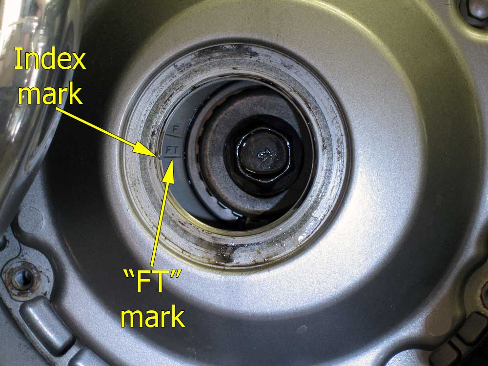
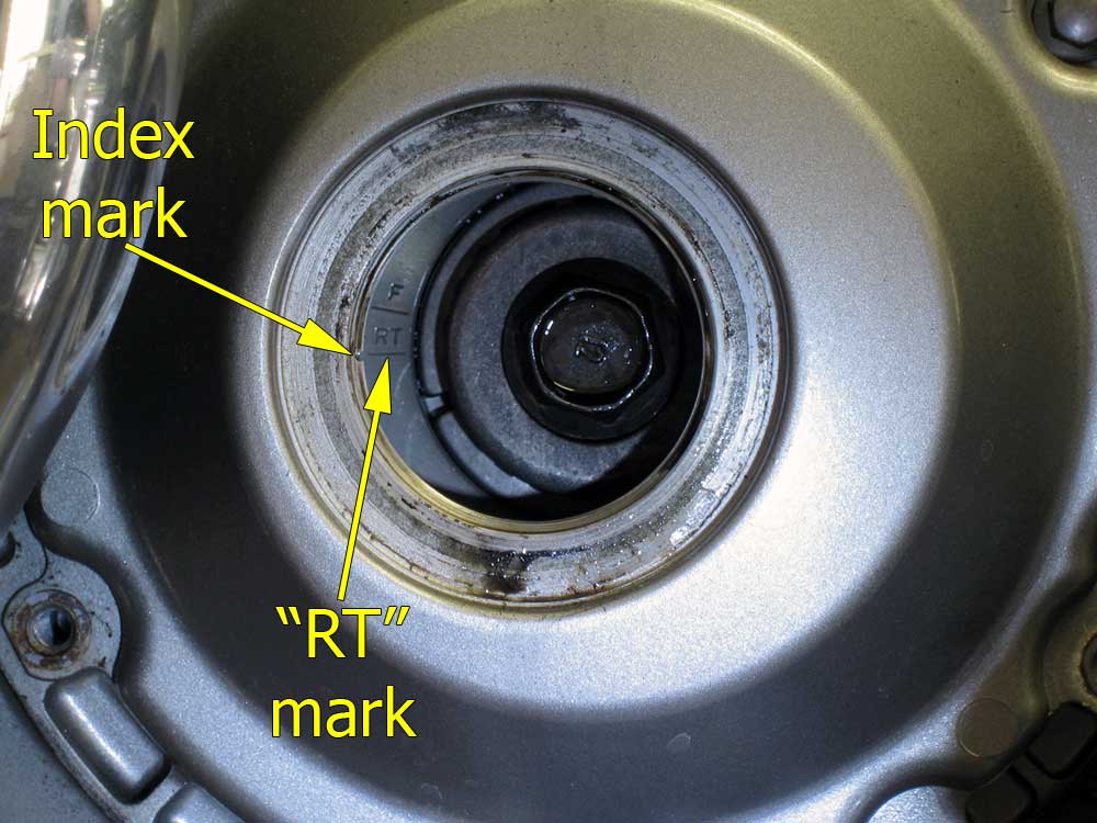
With everything torn down and out of the way we can now focus specifically on what we came to do and adjust the valves. Take a 17mm socket, an extension, a socket wrench and a flashlight and go down to the crankshaft. Notice the index mark at the 9 o’clock position of the hole. Using the 17mm socket spin the crank (clockwise) and you will see hashmarks on the crank (inside the cover) labeled “F” and “FT”, and “F” and “RT” (see pics below).
It is absolutely critical that you only spin the crankshaft clockwise.
There are auto-adjusting tensioners for the cam chains and if you turn the motor counter-clockwise it will (without getting technical) cause problems.

|

|
These marks indicate when each piston is at top dead center (TDC) during it’s cycle. In order to adjust the valves for either cylinder the piston in that cylinder has to be at TDC. This is pretty simple to remember:
“FT” is Front cylinder and “RT” is Rear cylinder.
To adjust the front cylinder’s valves spin the crankshaft until you line up the FT mark with the index mark. To adjust the rear cylinder’s valves spin the crankshaft until you line up the RT mark with the index mark. In order to do this properly you must be level with the index mark and the crankshaft, so really get down there and be sure you’re lining this up accurately.
With the proper mark (FT or RT) aligned with the index mark you have to be absolutely certain that the motor is at top dead center (TDC) of the compression stroke before you begin adjusting. Do this by grabbing any rocker arm for the proper cylinder and wiggling it. If it wiggles (it only wiggles a tiny bit) then you’re set. If it is rock solid (or if you’re unsure) then go back down to the crankshaft and rotate it with your socket one full revolution and re-align your marks. After this one revolution grab that rocker arm again and try to wiggle it. If it wiggles now then you’re good to move on. If it still seems solid then try rotating one full revolution again and re-check the rocker arms. It is only a slight wiggle so it usually helps to try both ways the first time so you can understand what we’re talking about and what you’re feeling for.
With the crankshaft at the proper mark and the rockers wiggling we can finally begin inspecting the valve clearances. The valve clearances on the VTX 1800 are .005″ +/- .001″ for the intake and .013″ +/- .001″ for the exhaust so get your feeler gauges, 10mm offset, and 4mm adjuster ready to go. Now I’m not going to waste your time and tell you that this is easy at first, but once you get the feel for the process it becomes very easy. The intake valves are reasonably easy to get to, it’s the exhaust valves that tend to be a hassle to figure out how to approach. I can’t tell you the exact way to go about it, I had to learn what worked for me. I have large hands and it’s a tight space, so it actually took me a long time to develop a method that works for me. Here are some things that work for me, you can try them and see if they work for you:
- I check the front cylinder from the right of the bike and the rear cylinder from the left
- When checking the front exhaust valve I add an extra bend in the feelers (you can kinda see it in the tools pic above)
- When checking the rear exhaust valve (the toughest one) I unbend the feelers, sit on the left of the bike, and bring the feelers in from the right side of the bike
| Rear valves looking from the left side of the bike: 
|
Front valves looking from the right side of the bike: 
|
| Click for larger pics | |
If you have no experience checking valve clearances then I would start with the intake valves since they are easier to get to and see what you’re doing. To check the intake valves you want to use your .004″, .005″, and .006″ feelers. The valve spec is .005″ +/- .001″ so before adjusting anything you want to use the .004″, .005″ and .006″ feelers to establish a starting point. If the .005″ doesn’t fit then try the .004″, if the .005″ does fit then try the .006″. The end goal is to have the .005″ fit snugly, while the .006″ will not go in and the .004″ fits with a slight drag.
Once you have an established idea of where the valves are, get out the 10mm offset wrench and the 4mm adjuster wrench. Use the 10mm offset wrench to loosen the locknut and use the 4mm wrench to turn the adjuster screw. The 4mm adjuster screw works just like any nut or bolt – clockwise tightens (reduces) the inspection gap and counter-clockwise loosens (expands) it. Always keep in mind that we are dealing with very slight variations in tolerance, so most adjustments only require turning the 4mm adjuster fractions of a turn to see results.
Once the inspection gap is large enough I like to put the .005″ feeler gauge in there and leave it while I make adjustments. It being there helps me feel when the adjuster is close to the right place AND it helps prevent the adjuster screw from rotating when I tighten the 10mm locknut. Once an adjustment is made hold the adjuster screw with your 4mm wrench while you snug the locknut with the 10mm offset. If you don’t hold the adjuster screw in place with the 4mm wrench then the process of snugging the locknut will also move the adjuster and change your setting. Keep in mind that you’re not overly tightening the locknut at this point, you just want it snug enough to prevent the 4mm adjuster from moving when you put the torque wrench on it.
With an adjustment made get out your torque wrench and tighten the 10mm locknut to 16 ft/lbs. I know it’s hard to believe, but you should be able to get a torque wrench and 10mm socket in there for every single valve except the rear exhaust. If you can’t get a torque wrench in there then just do your best – use the 10mm offset or a regular socket wrench but be sure the locknuts are good and snug. With the locknuts tight go back in with your feeler gauges and verify that your settings are correct, sometimes torquing the locknut can skew the gap slightly. Just like I mentioned above, the end goal is to have the .005″ fit snugly, while the .006″ will not go in and the .004″ fits with a slight drag. Don’t be afraid to get the feeler in the gap and use a finger to give it a little push to verify the gap. I use this method because I want to be certain that the valves are adjusted properly and I’d rather be too tight than too loose.
Once you believe you’re dialed in on the intake valves put away your .004″-.006″ feelers and get out the .012″, .013″ and .014″ feelers so you can check the exhaust valve. Now that you have a handle on the process it will make it easier to adjust the exhaust valve even though it is more difficult to see and get to. At least there is only one exhaust valve (per cylinder) instead of 2 like the intake valves. To adjust the exhaust valves follow the exact same procedures outlined above, just be sure you use the proper size feelers.
Once you have all the adjustments made go down to the crankshaft and turn the motor through several complete revolutions to cycle the motor and valves. Now repeat the entire process by setting the crank to the proper indexing mark and checking the valves again. If they are still perfectly within spec then you’re finished and can move onto reassembly – if not then spin the motor again and start over.
You need to repeat this process over and over for each cylinder until all 4 intake
valves and both exhaust valves are within spec.
Since the steps for adjusting every valve are basically the same I’ve put together this step-by-step that just runs through the basic procedure. If you’re experienced with this process then you can use this as a guide. Each number is a step, so just follow them in order.
- Spin the crankshaft (clockwise) and align the proper mark (FT for the front cylinder or RT for the rear cylinder) with the index mark
- Check that you are at top dead center on the compression stroke by wiggling any rocker arm in the cylinder you’re working on
- If the rocker arm doesn’t wiggle then turn the crankshaft one full revolution and line up the appropriate mark (FT or RT)
- Repeat steps 2 and 3 until the proper mark is aligned with the index mark and the proper cylinder’s rocker arms wiggle
- Check the valve clearances using .004″, .005″ and .006″ feelers for the intake valves and .012″, .013″, and .014″ feelers for the exhaust valves
- Use the 10mm offset wrench to loosen the locknut and the 4mm wrench to turn the adjuster to make adjustments to each valve (if necessary)
- When finished making adjustments, torque the locknut to 16 ft/lbs
- Repeat steps 5-7 until the valves are within spec – you want the proper feeler to fit, the size up to not fit, and the size down to fit with a slight drag
- Once you believe all the valves are adjusted, spin the crankshaft (clockwise) through several complete revolutions and start over from step 1
- Continue this entire process until all 6 valves require no adjustment after step 9
With the valves adjusted it’s all downhill from here…
Reassembly
Remove all the O-rings from all the inspection covers, you should have 4 valve inspection cover O-rings and 1 crankshaft cover O-ring:

Carefully clean and inspect these O-rings, if any are visibly damaged then replace them or you’ll have oil leaks. If they all look fine (and they usually do) then carefully coat them with silicone grease. If you don’t have silicone grease you can get by with a little clean engine oil, but the grease is better and will prolong the lifespan of the O-rings. You can sometimes find silicone grease at auto parts stores or industrial supply houses (Grainger), but when all else fails you can usually find it in the plumbing section of hardware stores or Home Depot/Lowes. Silicone grease is also used to repack faucets and plumbing fixtures. Be sure that what you get is grease, you want something in a tube or a tub – not a spray.
Now reinstall the O-rings into the covers and then reinstall the covers on the bike. Remember to install the covers first and the bolts second so the covers can prevent you from dropping a bolt inside the motor. The 8mm valve inspection cover bolts are tiny so don’t go over-tightening them or you may break them. They only need about 6 ft/lbs of torque to be set. The same applies to the crankshaft cover which only requires 13 ft/lbs of torque.
|
|
|
Put all the hoses, wires and hydraulic lines back where they belong and reinstall the zip-tie on the frame backbone that holds everything in place:
Reinstall the chrome timing cover:
Remove your radiator shim and reinstall the top radiator bolt:
Reinstall the rear ignition coil, remember the black wire w/ white stripe reattaches to the coil closest to the frame backbone. Reinstall the spark plugs using anti-seize on the threads and dielectric grease in the plug boots. If you have any questions about installing the plugs you can read the section titled “Proper Installation of Plugs” in my VTX spark plug article. With the spark plugs properly seated you can reinstall the chrome plug covers, the airbox, the gas tank, and the seat.
That’s it – you’re done – congratulations!
Afterthoughts
This is a daunting task for an inexperienced wrench turner to attempt, but after doing it a few times you quickly begin to see that the bulk of the work is really in getting the bike stripped down to get to the valves. I can’t stress how helpful it is to desmog the bike if it’s not done already. Having all that junk out of the way makes subsequent valve jobs that much easier.
I always recommend that riders learn to do their own maintenance and valve adjustments are no exception. In fact, I often think this is one of the most important jobs you can learn to do yourself. My reasoning is simple – If a shop lies to you about doing maintenance you can usually tell with a visual inspection. When we’re talking about adjusting valves, the only way to know if the job was done is to actually get into the motor and inspect them yourself – and if you’re going to do all that, then why take it to the shop at all?
I have (unfortunately) heard almost every kind of horror story there is about shop mechanics, and the sad truth is that you can never be sure a job is done properly unless you’ve done it yourself. I know for a fact that there are Honda dealerships who charge customers for valve jobs but just park the bike and return it to the customer having never touched it. I’ve also heard many, many, many times, where a shop mechanic will tell a customer that he can tell if the valves are within spec by “listening” to the motor. This is the dumbest thing I’ve ever heard and should be a giant red flag about the quality of work a shop does. The next time you get your hands on a set of feeler gauges find 2 that are .001″ apart and think really hard about if you could hear that small of a difference – because that .001″ is all it takes to be out of spec on a valve adjustment.
Video courtesy of Big Bad
This video is intended to give you an idea for the kind of things you’ll see and do during a valve adjustment on the VTX 1800. It is not intended to replace the above instructions for anyone except the most experienced mechanics because there are a few areas where it is lacking and minor mistakes are made.
Great site.
Great info, especially for us less technically inclined.
I really appreciate the effort you’ve put into these video segments.
Mike, Thanks for the info. I have been coming to your site before the start of all my VTX 1800 projects. PLEASE re-post your write-up instead of/or along with this video. Vid is ok, but some mistakes (mentions twice exhaust when it is the intake). Does not show the mother of all adjustments, the rear cylinder. Please re-post, Thanks for your time and efforts over all these years.
I appreciate the effort you put into this site, its been so helpful. I hate to pay for jobs that I can do myself. It gives me the satisfaction of knowing exactly what was done.
Thanks for the great write up and video.
Excellent! I am a professional racing and street mechanic and I thought your instructions were spot on! I even picked up something which I have never done before and that is a piece of string to tie the tools in case of dropping them into the motor. I have never done that before I guess I have just been lucky never dropped any tools inside the motor. I move very deliberately maybe even slowly. But I have some heavy gauge fishing line that I am going to try that with really always better safe than sorry. Thank you sir. Sincerely Eric Kent
Thanks again for the info. You’re site has been extremely helpful. Going to tackle valves this winter, while we are butt deep in snow up here in Wisconsin.
Excellent. This is the first time I’vee seen a start to finish valve job. Good tips, good demo. Maybe Ill give it a try.
very cool. thanks for yur effort. wasnt sure if i wanted to tackle this job until i saw the video. good to actually see what yur getting into. thanks
Thanks for the write up. I will do my own valves and save big time. The dealer said it would be a 10 hr. job @ $65 per hr. What a Crock. They were suposed to check them at the 8K inspection I doubth they did. I now have 20K on the bike and will know for sure.
Great write and video, thanks!! dirtstiff
Thank you for a well done ,HOW TOS,even this irish man can follow this,cheers from downunder.
As usual bare you have done a great job. Been following your guidance for years. Now if you only had a sight for for my harley..lol.
Hello,,,,Thumbs up from Denmark
Great video, easy to follow and good comments. BIG help.
Nice wright up with the step by step instructions for us do it your selfers,i was going to have the dealer do this but i will do it my self now.thank you
I hope your not spewing crap , cause here we go in valve adjustment
I’ve finished my first valve adjustment and did the desmog, as well, before I tackled the valves. I worked slowly and carefully, and it took me a very long time. However, your instructions were invauluable. I really appreciated all of the extra tips. Before I do the job again, I am going to figure out some way to make working on that rear exhaust valve easier. That was rediculous!!! Thanks for the help.
Great info, Im a new vtx 1800 owner mine has 7100 miles and I was wondering how often dose the valve train need to be adjusted or checked? Also i liked your info on oil changes, thanks for your help. My best friend has a 1300 vtx he bought new and had the dealer do his maintence, partially because it was included with the purchase, and he is finding out now they didnt do all they said or what was required. Damage DONE! be careful.
https://tech.bareasschoppers.com/resources/maintenance-schedules/
One of the best no BS directional write-ups I have read! I am saving it and I will use it very soon. Thank you.
Thanks Bare! My valve train has been really noisy since the purchase of my 2002C. This is an awesome write up and I could not have completed the valve adjustment with out using it. The service manual leaves a lot to be desired.
From the tools required, to your recommendations and afterthoughts it really helped tremendously. I would have probably completed the teardown and then trailered her to my local stealer if now for this!
I’ll be back for more soon!
I am a mechanic for the military and I wish you were writing all of or technical manuals. This is one of the most thorough and easily understood maintenance procedures I have read. (Over 17 years I have read a bunch). I recently bought a VTX1800 and am currently waiting on a Honda service manual so I can go over my bike. After reading this I am going to go ahead and do my valve adjustment instead of waiting for the service manual. Thanks for this.
[…] The top end on these engines are pretty noisy. If it’s limited to a tick, you are probably okay. As these engines wear, the valves tighten up. So it’s really when they go quiet you need to start thinking about service. […]
[…] […]
This is my second time doing the valve adjustment and can’t thank you guys enough. The detail was incredibly great! After doing it once, the second time was much easier. But the best part was the feel of the engine. The desmog and all the little changes recommended made this a great ride.
[…] was working, something about touching my phone with oil covered hands… I used a photo above from a really great VTX valve DIY article I found. In any case, based on what I saw when I got it opened up, I’m fairly certain I was the first one […]
Just want to give you a suggestion. The part (valve adjustment) where you say to take the top radiator bolt off and shim it away 1 to 2 inches. I STRONGLY suggest to put in there also to at least loosen the bottom two bolts also because I did not..
I only followed these instructions and ended up cracking the weld on the bottom mount where the bolt is and ended up having to order a new radiator.
Thanks for so much for all you’ve done over the years for us VTXers, and thanks even more for this walk through in particular.
Came here to let latecomers know that USA manufacturer Bondhus makes a stubby Allen set that allowed me to get the timing cover off my 2003 1800 C without having to loosen my Vance & Hines Big Shots.
Bondhus 9-piece stubby double ball Allen wrenches, p/n 67099 SDBLX9MXL, lifetime warranty from the manufacturer, $18 at Northern Tool with a lifetime warranty. Pic: https://imgur.com/gallery/H2BjnHM
This How-to is still relevant today. Perhaps more so, in that all the mechanics that have actually adjusted lifters on a VTX 1800 have probably retired or passed. We are on our own as most shops won’t touch anything over 10 years old.
Thank you for this site. My only fear is I will come back, desperate, and find all this knowledge gone. How do I save all the How-tos for my grandson in the future?
Thanks, again.
I am attempting a valve clearance inspection on my 02 vtx1800c. Checking the clearance I find that it’s too tight. I can’t even get the .oo4 in the gap. It’s been parked for a while, but it was running okay when I parked it. So I’m not sure what to do now. Should I leave it like it is or increase the clearance to specs?
Thanks Dan
This has been extremely helpful thank you for putting this together and keeping it active. I scoffed at the string on the tools until it bit me and I dropped a feeler gauge…. luckily a long pair of pliers saved the day but I have been scared straight! DO NOT SKIP TYING YOUR TOOLS!