VTX 1800C Diode Fix
Posted by Bare | Last Updated March 19, 2015These are specific directions for installing a “diode kit” on a Honda VTX 1800C model, but this actually applies to almost every motorcycle that has a single dash indicator for both left and right blinkers. This kit is available from Kuryakyn (part #4709) or I have details on how to build your own. The diode kit cures problems inherent with the design of the dash light circuit when you install LED blinkers. Let me apologize now, this write up was done long after I’d added my own diode kit in an effort to help others having problems, so this article is not as thorough as many others I’ve done. I just couldn’t see tearing my wire harness open again to snap pictures.
This project affects parts of the electrical system on your bike so if you should decide to undertake this task you will need the tools and know-how to solder wires together and seal them with heat shrink and/or electrical tape. If you are unsure of what you are doing this project could result in damage to your bike’s electrical system. Any similar work performed on your vehicle is done at your own risk. With that said, this is not a very difficult task if you have basic electronics skills. You just need to be careful and take your time.
Now, you may be wondering – why do I need a diode on my bike when I change to LED blinkers?
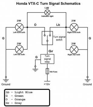
To understand and explain this thoroughly I think a schematic of the Honda turn signal setup will help (see inset).
What makes this circuit different from other bikes is that it has only one indicator light on the dash to let you know the blinker is on. Other bikes with 2 dash lights – one for each side – eliminate the cause of the problem.
To better understand this you first need to understand how a basic DC (direct current) electrical circuit works. Take for example just the right hand side of the schematic above, disregarding the indicator light. Power comes from the 12V supply (your battery) through a 10A fuse which is designed to protect the circuit if there is a “short” in it. It then goes past the fuse to the relay which determines the rate at which the signal flashes, and then to the switch which is what actually turns the circuit on and off. With the switch in the “on” position (in the schematic it is “off”) the circuit is completed and power is allowed to flow from the battery, through the fuse, relay, switch and into the “load” (the blinker bulbs in this case) and then finally to ground.
The important thing to learn from this is that in order for any circuit to function it needs to be complete from 12V all the way to ground. The switch in this circuit is what allows power to flow and the blinkers to blink.
With this basic understanding of how circuits work it will help to understand how this one indicator light functions. By having only one indicator light you can see that it must get power from either the left or right side in order to blink. The problem is that Honda designed this system in such a way that when the left blinker goes on it provides power to the indicator light which then finds its electronic ground (to complete the circuit) through the right side of the circuit – and vice-versa for the right blinker. If that confuses you then look at the diagram above and cover up everything on the right side. With the switch flipped to the left the right side of the circuit doesn’t function BUT the indicator light uses it as a way to find its ground so it can light up.
Once you understand how the indicator light gets its power from each side of the circuit then you can see how a small amount of power is “leaking” over from one side to the other. This small “leak” doesn’t matter when you have the stock incandescent bulbs or even aftermarket halogens because they require more power to light up than the little indicator light can “leak” to them. LED signals on the other hand only require very small amounts of power to light up and the indicator light DOES leak enough power to light these. So instead of hitting the left blinker button and getting a left blinker, you get “emergency flashers” with all 4 lights blinking together.
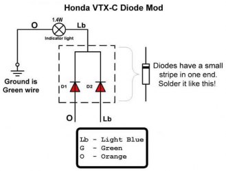
So therein lies the problem – how do you get the indicator light to still function with LED signals based on the design of Honda’s circuit? The answer is to modify the circuit – like the picture on the right. This schematic shows how to rewire the indicator light portion of the circuit. Using a diode kit or your own diodes to fix the circuit so that no “feedback” can occur from one side to the other. The section of the circuit inside the dashed box represents the diodes you’re adding to the circuit.
To better understand diodes, think of them as a one-way valve for electricity. They let power through in one direction only. In this case it lets power get to the indicator light but the power cannot flow back behind the diodes.
Required tools/Materials
- 5mm allen
- Wire cutters
- Wire strippers
- Philips head screwdriver
- Soldering iron & solder
- Electrical tape or heat shrink tubing
- Kuryakyn #4709 (diode kit) or Two 3 amp diodes
For years I recommended buying your parts for this from Radio Shack out of convenience, but with them out of business you’re somewhat left to your own devices to find these parts. Check locally for small electronics shops or do an internet search for the specific parts (listed below) and it should be relatively easy and inexpensive to find what you need.
Removing the dash
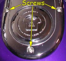
To start, you’ll need to get to the wire harness that runs under your dash panel for all the warning lights. Remove the dash panel by removing the three 5mm screws closest to the seat (see pic). Be careful not to lose the almost invisible nylon washers that come off with these screws. Once the screws are out you’ll have to take off your gas cap to pull the dash off.
NOTE: Leave the gas cap on until you get all the screws out and away from the dash – this way you ensure you do not drop the screws IN the gas tank!
With the gas cap removed, slide the dash forward to get it off of the little tab it sits on at the front of the tank. Make sure you do not lose the little rubber cover that sits on this tab, it helps prevents your dash panel from rattling.
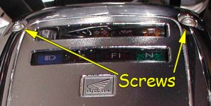
With the dash panel removed from the tank remove these two 5mm screws:
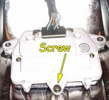
Then flip the dash panel over and remove this one here with a philips screwdriver:
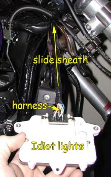
Removing the “light box” from the dash panel makes working on this much easier and eliminates any chances of damaging the chrome finish on the dash.
Wiring the diode
Now that you’ve got the dash off you can concentrate on the wiring. There will be electrical tape wrapped around the harness to hold the black sheath on. Peel it back (I don’t recommend cutting it off because of the wires!) and slide back the black plastic sheathing on the wire harness.
By pulling back the sheathing you can get to the wires you need and still have enough room to work with them – plus when you are done you can slide the sheathing right back over the wires and it will look like nothing was done. I found it very helpful to use a spring clamp (like a giant clothespin) to hold the sheathing out of the way once it is pulled back.
With the wires accessible find the green, orange and light blue wires in the harness and separate them from the others so you can work with them. Next, you’ll need to cut the orange and light blue wires making sure to leave enough slack to work with on both sides of the cut.
Read this part carefully…
With the orange and light blue wires cut, strip the insulation from the orange wire coming FROM the dash lights and splice it into the green wire in the harness. This green wire is your bike’s ground and you want to tap this wire into that ground. Once you solder the orange wire into the green, heat shrink the connection or wrap it tightly with electrical tape.
Now you have 3 wires left, 2 coming from the bike (orange and light blue) and the light blue wire coming from the dash lights. You have to decide whether you are using the Kuryakyn premade diode kit or if you are making your own kit.
Kuryakyn diode kit
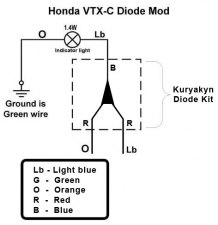
The Kuryakyn diode kit has 1 blue wire and 2 red wires. You want to solder and heat shrink the 2 red wires from the diode to the orange and light blue wire coming from the bike. When you’ve completed this step, you will have one orange wire coming from the bike soldered/heat shrunk to a red lead from the diode and one blue wire coming from the bike soldered/heat shrunk to the other red lead from the diode. Once this is done you only have the blue wire from the diode and light blue wire coming from the dash lights. Solder/heat shrink these 2 wires together and you are done.
When you are finished you should have a circuit just like the pic on the left.
Now you can skip this next section and go down to “Finishing Up“.
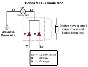
If you bought your own diodes then you have a little prep work before you can install them. What you’re going to do is build what Kuryakyn sells you for several times the price. Take the 2 diodes and find the stripe on them. Put both stripes pointing in the same direction with both diodes side by side and twist the leads on the striped end together. Take these now connected leads and solder them to the light blue wire coming from the dash panel. With that completed, you have the 2 opposite ends of the diodes which are currently not connected. Solder one of these to the orange wire and the other to the light blue wire. Be sure and heat shrink or electrical tape these connections well. You don’t want any of these leads shorting out against each other.
When you are finished you should have a circuit just like this picture.
Finishing up
At this point it would be wise to test your blinkers to make sure they work properly. If they work, then you just need to clean up the wire harness – make sure all your connections are solid and well-sealed, then slide the black plastic sheathing back over the entire harness. If they do not work then retrace the steps and check all your connections. Wrap a little electrical tape around the end of the sheath just like what you took off when you started. Then reverse the steps above to put your dash back together and on the bike.
Afterthoughts
I want to mention that this is not strictly a problem with the VTX 1800C model. I have seen this same problem on other motorcycles that have a single signal indicator on the dash. So if you have a friend who just replaced his blinkers with LED’s and has a single dash light with this problem – consider looking into these diodes as a solution.

thanks a heap for the time and effort you put in creating this page. I had this problem and it had me stuffed for ages untill I found this. love your work. ken , Gold Coast Australia
Hey: GRE8T job on the VTX 1800C turn signal wiring diagram. I’ve been looking for this for a long time. Been messing with LED’s and incondenscent add on lights to my VTX and fried my LED flasher. Got a new one from Dennis Kirk, and it was only marked G….L….P….{+}…Now I had figured out that G was for GROUND on the Honda, but what was Power {+} and what was T/S Main wire. Had a white and a gray coming from the bikes harness, and your drawing told me exactly where to put my leads. THANK YOU…one thing I would like to see…is what color is the POWER {+} wire coming from the bike….hopefully it’s WHITW with black markers. Regards Elmer W. Ingram, Jr.
I also had the same problem an doing this mod was a piece of cake that fixed the problem of bleed power over
Just wanted to say thanks for such a well written piece!
[…] best description I’ve seen on this issue and its solution is an article entitled “VTX 1800C Diode Fix” on the “Bareass Choppers” (you read that right!) website. Read the article […]
Great instructions for a great fix
This was great. I worked on my bike for two days before finding this article. I had the led lights working and my bike on the road in hour after reading this article. Thanks for the help
Realllllllllly helped! I have a 1957 beetle converted to a meyers manx, I just redid the dash, speedometer and indicator signals. I ran into this same problem and the radio shack setup is the one for me. Thank you for the great write up.
great fix did the radio shack version cost me 1.99
Thanks for this great info, I used it to sort out a problem with my land rover led’s that were back feeding opperating all 4 flashers, once agsin thank you, Steve UK.
I opted to just cut, & cap off, the orange and light blue ,indicator lamp wires.
This also free’s up the wattage of the indicator lamp.
The front signal lights are so bright. I use them as my turn signal indicators.
Also you don’t have to worry about messing up your electrical system.
When I first used the diode’s. My tach & TPS started malfunctioning.
I put all back to stock, and got everything working proper.
Had steelmetal flasher for yamaha, the first try. Got the Honda flasher & eliminated the indicator lamp.
Now it works great!!!
My bad that’s
SPEEDMETAL Flash LED Relay:
Not steelmetal flasher.
If you want the “Rear Running Lights Mod”, to work properly. The diode fix should be done. Otherwise the running lights go dim at idle, without the dash turn indicator lamp connected. I attempted to rewire the dash to have separate turn signal indicators. Led lamp did not work. It has to be incandescent, and it has to match the existing lamp. If wired this way. The running/brake/turn signals work independent of each other. In other words. When one signal light is turned on. The other one will not blink off.
My previously mentioned, electrical malfunctions had nothing to do with the “VTX 1800C Diode Fix”. The mod is solid, and if done properly works great! The only thing is that now my turn signal indicator, dimly lights up when the brakes are applied. And that’s fine by me.
Bare thank you so very much! For this and all the other write up’s you’ve done. They are all great! Thanks!
[…]I found a write up on a different board pretty helpful — turned out to help me fully understand what I needed to do.[…]
hi . thank you very very much .
[…]The best description I’ve seen on this issue and its solution is an article entitled “VTX 1800C Diode Fix” on the “Bareass Choppers” (you read that right!) website.[…]
I managed to solve turn indicator problem thanks to your detailed explanation. Solution with diodes works great on my GS500E from 1992. , even with led flasher relay turn indicator did not work. I used UF 5404 diodes from some junk electronic board. Thank you very much!
Great write-up with great pictures, thank you.
I just wanted to point out two details that might not be well known:
1) You do not need 3A diodes since they power only a 1.5W bulb, you can use 200mA diodes with no problems but the most commonly found diodes are rated at 1A and they will do just fine.
2) The mod can be done any time, regardless of LEDs or running lights. Even if you have none of those mods, this diode mod will not hurt anything, it is actually a preferred method of indication.
Cheers.
My younger self would have told my current self to have done this many years ago. He would have also reminded me that I had taken out the turn signal dash bulb about ten years ago so I would have avoided a lot of head scratching and re-soldering all my connections before remembering it was buried deep in a parts box. Delighted to have finally got it going, no more thumbing the centre point of the switch, ‘just incase.’
Thanks for the great write up that helped this soldering novice get it together!
Thanks to the original poster for this. Great details for getting ALL the LEDs working right on a 2001 Valkyrie.
Bare,
Your description made it easy to do, and understand why
Thanks
All new LEDs work great now
I did this fix, my indicators are working but my fash light stays on. I’m stumped.
Sorry, I meant indicator light on my dash.